

Secure Workload and Secure Firewall – Unified Segmentation
May 28, 2021
Microsoft launches first Asia Pacific Public Sector Cyber Security Executive Council across seven markets in the region
June 1, 2021Cisco Secure Firewall insertion using Cisco cAPIC in Azure

In today’s world, enterprises are undergoing a transition to innovate rapidly, keep up with the competition, and increase application agility to meet ever-changing customer demands. To achieve these goals, they often choose the hybrid cloud infrastructure approach, choosing different infrastructure environments to deploy different types of applications. Some applications are best suited for hosting on-premises, whereas others are better suited for hosting in public cloud. Thus, hybrid cloud is the new normal for many organizations. However, in a hybrid cloud environment, the challenge is to maintain a uniform enterprise operational model, comply with corporate security policies, and gain visibility across the hybrid environments.
Cisco Cloud Application Centric Infrastructure (Cisco Cloud ACI) is a comprehensive solution that provides:
- simplified operations
- consistent security policy management
- visibility across multiple on-premises data centers and public clouds or hybrid cloud environments
- unified security policy for the hybrid cloud
- extends on-premises layer-7 security to public cloud
In an on-premises Cisco ACI data center, Cisco Application Policy Infrastructure Controller (APIC) is the single point of policy configuration and management for all the Cisco ACI switches deployed in the data center. Cisco ACI multi-site orchestrator (MSO) provides a seamless way to interconnect multiple cisco ACI data centers. MSO is a software solution representing a single point of policy orchestration and visibility across multiple geographically dispersed ACI sites.
Cisco Cloud APIC runs natively on supported public clouds to provide automated connectivity, policy translation, and enhanced visibility of workloads in the public cloud. Cisco Cloud APIC translates all the policies received from MSO and programs them into cloud-native constructs such as VNets (Virtual Network), application security groups, network security groups, outbound rules, inbound rules, etc. This new solution brings a suite of capabilities to extend on-premises data centers into true hybrid cloud architectures, helping drive policy and operational consistency regardless of where your applications reside. Also, it provides a single point of policy orchestration across hybrid environments, operational consistency, and visibility across clouds.
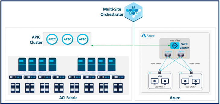
Figure 1 above shows the overall high-level architecture of Cisco Cloud ACI with Cisco ACI Multi-Site Orchestrator acting as a central policy controller, managing policies across on-premises Cisco ACI data centers, as well as Azure environment with each cloud site being abstracted by its own Cloud APICs.
Traditional firewall integration in on-prem Data Centers
To enable scalable and manageable network security in larger data center networks, on-prem Cisco Secure Firewalls (ASA and FTD) are integrated as “unmanaged” firewall (Cisco ASAv and FTDv/NGFWv) devices into existing ACI deployments. While existing ACI contracts can be easily leveraged for enforcing security policies within a single network security zone, insertion of ASA/FTD firewalls allows for segmented workload security for inter-zone traffic, thus reducing the load on leaf ACI switches.
Hybrid Cloud
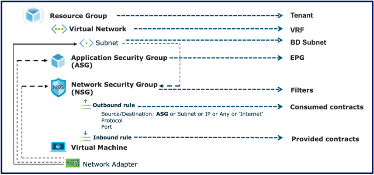
The modern data center is a hybrid ecosystem, where some applications reside in classic on-prem environments, others are hosted in public cloud environments, or are co-located in both. Cisco cloud ACI provides a uniform mechanism for data center operations, policy management, and visibility in a similar data center environment spanning multiple on-prem, cloud, and hybrid infrastructure components. To seamlessly navigate between ACI-aware data centers and cloud-native environments like AWS or Azure, the Cisco cloud application policy infrastructure controller (cAPIC) functions as a universal translator that maps ACI-specific constructs (like service graphs or contracts) into CSP-specific language (like end-point groups or VPCs).
End-point groups (EPGs) represent applications running in the cloud, on-prem or hybrid environments. Service graphs represent L4-L7 devices inserted between EPGs, with ACI contracts and filtering rules defining inter-EPG communication scope and boundaries. cAPIC avails user-defined routing (UDR) to automatically obtain network or application-centric security rules based on the specific policy configuration and contracts that apply to different EPGs. While cAPIC automatically configures the network needs of most elements in a service graph, cloud-native firewalls (like on-prem firewalls in a traditional ACI-aware data center) are considered as unmanaged entities with firewall configuration managed outside of cAPIC.
NOTE: Granular and accurate mapping between these two network policy models is crucial to ensure the correct deployment of network policies across Cisco ACI and Microsoft Azure. Figure 2 below shows how Cloud APIC handles this policy mapping.
Securing Azure with virtual ASA and FTD solutions
Cisco validated architecture for ASAv and NGFWv insertion in Azure using Cisco cAPIC L7 insertion. The following deployment scenarios have been validated as part of this effort.
- Multi-node (NGFWv LB sandwich)
- North/South and East/West traffic flow
Use case 1: Spoke to Internet (N/S traffic flows)
Test Scenario: Traffic from the workload destined to the internet is forwarded to Azure internal load balancer (ILB). ILB load balances traffic from the consumer EPGs to the internet through multiple Cisco Secure Firewalls (NGFWv).

The above network topology depicts Cisco Secure Firewall in the hub VNET (overlay 2) in Azure. We have a service graph with ILB redirect to Cisco Secure Firewalls.
Traffic Flow
- The consumer sends traffic to ILB.
- ILB receives traffic and forwards traffic to the firewall
Firewall receives traffic, applies security policy, and sends it out via outside interface. Outbound traffic is SNAT on the firewall.
Consumer —— > NLB [redir ] + FTD[SNAT ] ———- > Internet
Use case 2: Spoke to spoke multi-node inter-VPC, intra-region traffic flow enablement
Test scenario: Traffic from consumer EPG to provider EPS is load-balanced through multiple Cisco Secure Firewalls.

The above network topology depicts Cisco Secure Firewall in the hub VNET (overlay 2) in Azure. We use service graph with Network load balancer redirect, Cisco Secure Firewall and Application load balancer.
Traffic flow
- The consumer sends traffic to ILB.
- ILB receives traffic and forwards traffic to the firewall
- Firewall receives traffic, applies security policy, and sends it to ALB
- ALB then sends it to provide (workloads).
Consumer —— > NLB [redir ] + FTD [SNAT] ———- > [ ALB —- > Multiple Provider]
Resources
We’d love to hear what you think. Ask a Question, Comment Below, and Stay Connected with Cisco Secure on social!
Cisco Secure Social Channels
Instagram
Facebook
Twitter
LinkedIn